
Diode Protection Circuits. Diagram A This circuit consists of a relay coil

The main advantage of this circuit is that it works with a voltage as low as

Although this form of the single balanced diode mixer circuit does require a
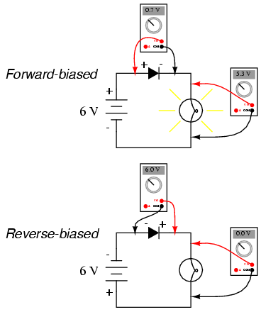
simple battery-diode-lamp circuit shown earlier, this time investigating

The circuit of this diode current limiter for a power supply is particularly
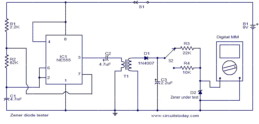
The Zener diode is a fine one; the meter will show the correct Zener voltage

Source url:http://magickaldreams.com/ut/dv-downloadable-diode-circuits.htm

circuits to drive their laser diodes. As an example, Figure 1 shows a
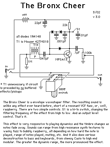
Simple diode clippers and distortion circuits
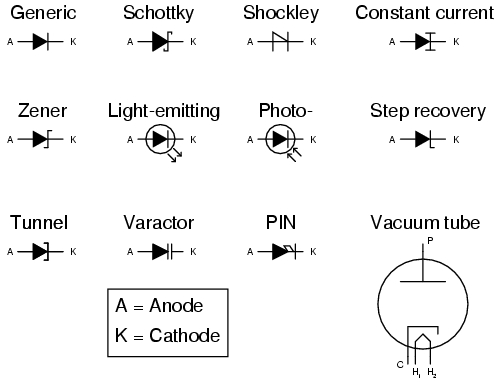
Diodes : CIRCUIT SCHEMATIC SYMBOLS

b) 3 rectifier diodes as voltage regulator. Suitable only for very low power
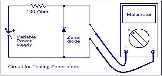
How to test a diode - Electronic Circuits-Circuit Diagram-Electronics

Below are 3 circuit diagrams illustrating the usage of diodes.

This is a PIN diode based attenuator circuit operates with 1MHz - 500MHz

A double balanced diode mixer circuit
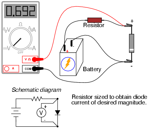
Connecting the diode backwards to this testing circuit will simply result in

Clamping Diode Circuit A family of curves for different values of DC base

The following circuit diagram show the most basic LED (Light Emitting Diode)

Atomtronic analogy to a simple diode circuit. The atomtronic analogy of a

Rectifier circuit using four diodes; Full-wave Bridge Rectifier.


0 comments:
Post a Comment